CD009 TRANSMISSION IN S-CHASSIS
The S-chassis most popular engine is the venerable SR20DET that is capable of producing high power and torque output from a small displacement block that can be modified for more reliability. The transmission is however not up to the task of reliably handling torque values above 400 foot pounds or 550Nm as the FS5W71C code can be traced back to Nissan-Datsun cars of the early 1970s. The gear-set kits offered for this gearbox are also not much stronger as the maximum transmittable torque is limited by the diameter of the shafts. The six speed close ratio transmission found in the S15 has even lower maximum torque rating than the 5-speed of the older generation S chassis’.
The 350Z debuted with a new CD000 gearbox that is significantly stronger and features 6 closely matched ratios that are perfect for a small displacement engines with a narrow torque band such as the SR20DET and has thus become a popular upgrade.

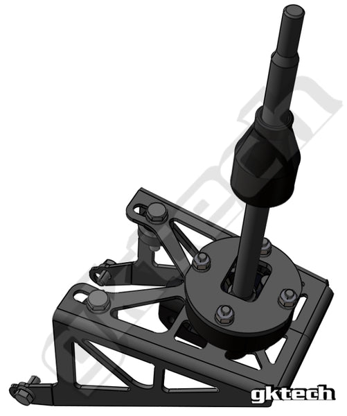
Image 1 - GKtech CD009 shifter
1. CD00x SHIFTER LOCATION PROBLEM
Installation and replacement of several components is required to install the CD00x transmission to the SR20DET. One of those is the shifter.
The main issue with the OEM 350Z shifter system is that it sits about 160mm too far from the center of the original hole for the original 5 speed transmission that was factory fitted.
At the start of the project there were no suitable versions available on the market that allowed for shifter installation on the CD009 transmission in the original position or near it without modifying the chassis or requiring custom fabrication.

Image 2 – Shifter position with OEM shifter bracket

Image 3 – shifter shaft position relative to S chassis shifter hole
2. CONCEPT
Solutions were available on the market at the start of this project but all had a few centimeters missing from the optimal shifter location due to utilizing modified shifter linkage that was made as short as possible by cutting out the center tube and welding the U shaped universal joint ends together. This allowed the shifter to be pushed forward substantially, but not enough to not cut the chassis. Also many of these kits were incomplete or required modifications to OEM components or chassis.
Some DIY systems had relocated the shifter on top of the gearbox with a reversed linkage. The problem with this is that the shifter is mounted very high and still retains the linkage.
Some Nissan trucks (i.e. 2008 Xterra) that used this transmission featured a shifter in place of the black cover plate on top of the transmission (image 4). This concept was to be too far forward for S chassis installation unless the engine has been moved through the firewall. It did however provide the idea for the final product.
Based on this information it was decided to design a new shifter assembly. It was also required for one of our own project cars, that would be future test bed for this product. The following design parameters were set:
- Position the new shifter as concentric to S-chassis shifter hole as possible
- Retain reverse gear lock-out as it is next to gears 5-6
- Short shift operation with good shift feel
- Minimal number of components
- Lightweight construction
- Retain dust covers
- Easy to install

Image 4 – CD00A transmission
3. NEW PRODUCT
3.1 MEASURING AND MODELING
The new shifter is to be designed with the same operating principle as the S-chassis gearbox shifter, since this offers a compact solution to mount the shifter in the desired position, right in the center of the original gearbox shifter hole. The 350Z shifter uses a shaft that has a universal joint on it so reverse lockout can be used as the shifter lever needs to be pushed down to engage reverse gear. The S chassis version uses a shifter fork directly attached to the gear selecting shaft and is a cost effective solution for this project if the U-joint shaft system can’t be made short enough.
The coordinates for the bolt holes were measured from the 350Z shifter bracket to mock up the OEM shifter. The shifter shaft position was measured off the gearbox in relation to the bolt holes and was positioned in CAD based on these dimensions.

Image 5 – OEM shifter bracket mounts and shifter
3.2 FIRST CONCEPT
The first concept explored was a simple version with a new U-joint clevis that tied the shifter as close to the U-joint as possible. The result was 126mm shifter relocation, which was about 10mm better than other shifters available, but still it would have required cutting of the chassis.

Image 6 – V1 shifter concept in blue compared to grey OEM
3.3 SECOND CONCEPT
The second concept was a complete redesign with the gear shift linkage removed and replaced with a fork style fulcrum instead. This is how the S-chassis original gearbox works inside the gearbox. The shifter relocation from original mounting position on the gearbox was now 160mm forward and it was now in the same place as with the original gearbox.
The next step was to design the reverse lockout functionality and lever kinematics that allow for easy and precise shifting without the risk of miss-shifting as short shifters that have too short throws are difficult to use on the race track and should be avoid. A miss-shift during a race can lead to a damaged gearbox and negatively affect the outcome.

Image 7 – Shifter’s final position
3.4 SHIFTER DESIGN
Early in the design process it was decided to try to use the S-chassis shifter lever along with OEM components it utlises such as the plastic cups. This was done to make the shifter assembly cost efficient and limit the amount of bespoke parts.
Reverse lockout feature was missing from this design stage as getting the shifter kinematics right was more important.
The shifter housing was done in two pieces. A steel bracket was designed for mounting the assembly to the gearbox and a lightweight machined aluminium part to house the shifter. The shifter was fixed the same way as in the S-chassis short shifter as the same lever was used.

Image 8 – first prototype
3.5 PROTOTYPING
3.5.1 FIRST PROTOTYPE
The use of the S-chassis short shifter lever resulted in a very short lateral throw and selecting gears on different selector shafts was difficult to do as it had to have to been done precisely and with minimal movement of the wrist. It would make fast driving difficult as miss-shifts could happen easily. The shifter position would need to be optimised for the next stage.
There was also mounting bracket interference with some of the components on the gearbox housing.
Aside from the too short throw there were also problems with clearances between the components. The fork made contact with the shifter lever’s housing and the design was updated to move the fork closer to the gearbox and trim off the end of the selector shaft. This modification requires shortening the OEM selector shaft to be flush with the fork. Housing diameter and spring diameter would have to be decreased.

Image 9 – Fork contact with shifter housing
3.5.2 SECOND DESIGN UPDATE AND PROTOTYPE
Second prototype featured many changes. The mounting bracket was designed with more clearance to the surrounding elements on the gearbox. Its height relative to the center of the gear selector shaft was also changed. CD009 transmission (gearbox) specific lever was designed and the pivoting height lowered for more side throw. The plastic OEM parts around the shifter lever were installed upside down to enable the reverse lockout feature. In hindsight this was not a good idea as the shifter locating plastic cups separate during spring compression and need to be joined together for the next version.
The shifter lever housing was sunk deeper into the mounting bracket and turned 180° for more hardware clearance from the shifter fork. The reverse lockout spring was added to this version. This also required a pin to be installed on the shifter lever.
The side throw in this version was also too short and another complaint from testing personnel was that the reverse lockout spring was too stiff. The nut on the rear of the reverse lockout plate was also touching the chassis and needs to be downsized and relocated forward.

Image 10 – second prototype in CAD

Image 11 – second prototype fitted
3.5.3 THIRD DESIGN UPDATE AND PROTOTYPE
Third version featured a major redesign with every component updated to improve functionality and fitment. There were no OEM components used in this version as it was a clean slate design.
Side throw was increased and now much closer to what OEM shifter feels like. Reverse lockout spring was quite good, but could have been softer. Position in the transmission tunnel was ideal.

Image 12 – third prototype by design

Image 13 – Third prototype in form
3.5.4 FOURTH DESIGN UPDATE AND PROTOTYPE
Fourth prototype was the last one before production. All the minor changes requested from testers were done to ensure the shifter works perfectly. The shifter was moved rearwards for more clearance from the shifter shaft fork and reverse lockout spring rate reduced further. Reverse lockout pin was redesigned for smoother engagement and more wear resistance.
This version functioned as intended and only slight changes were made before going into production such as more weight to strength optimised components for less weight and less play.

Image 14 – fourth prototype by design

Image 15 – Final prototype fork clearance from shifter lever housing
4. PRODUCTION VERSION
The first widely available production version was released after 1.5 years of prototyping and testing. The idea behind this product was to make it as perfect as possible as with all GKtech products.
The production version had the following features and benefits:
- 154mm forwarded shifter position relative to 350Z shifter on CD009 transmission to make it fit into S-chassis without chassis modifications
- Reverse gear lockout feature with a high quality spring and adjustable position
- Solid feeling and strong shifter lever with comfortable throw without slop
- Lightweight and strong laser cut and CNC formed mounting bracket
- Lightweight FEA optimised and CAD designed from the ground up
- Lightweight billet 6061-T6 aluminium shifter housing
- Bronze bottom shifter bushing
- Easy to install

Image 16 – first production version
5. CONTINUOUS IMPROVEMENTS
Several upgrades have been made to the shifter assembly ever since the original release, which are the following:
- Two plastic semi-spheres now integrated to the shifter lever for more stiffness and strength
- Shifter lever diameter has been increased in critical areas for more strength
- Mounting bracket now supports older versions of CD009 transmissions that has shifter mounting points closer to the bottom of the gearbox
- Reverse lockout mechanism strength has been improved against wear
- Shifter lever is now delivered pre-assembled

Image 17 – Latest version
6. CONCLUSION
In conclusion this has been one of the longest on-going projects at GKtech, but after two years of prototyping and continuous improvements the current production version is what we feel as the best on the market.
It is easy to install as it is delivered with a pre-assembled shifter assembly and the end user is required to mount the bracket and assemble the shifter to the housing and then adjust the reverse lock-out plate location. It is necessary to trim the end of the gear selector shaft that comes out of the gearbox flush with the fork that goes over the shaft and fixed in place with a spring pin.
It has very positive gear engagement with good amount of throw between gears and durable enough for any kind of use. It has constantly been improved and will be throughout its production lifetime to make it the best possible product.
This shifter can also be used on other chassis and engine combinations that benefit from the CD00x gearbox swap as this gearbox has been proven to handle engine torque outputs up to 1200Nm / 900 ft-lbs reliability and can be purchased brand new at a reasonable cost.
It is advisable to prefer as late model version as possible as early versions before CD005 have hard gear engagement due to having less synchromesh engagement. The first two gears on pre-CD005 feature double cone synchronizer and starting with CD005 third and fourth are also double cone synchronized. Versions more new than the CD006 feature triple cone synchronizers. The latest version is CD00A and is currently the best one available.

Image 18 – Production version assembly sketch
Author: Siim Õisma
Bsc Automotive engineering, Msc (in training) Product development
GKtech engineer since 2013
USA store product link - V2 Z33/Z34 TRANSMISSION SHIFTER RELOCATION SETUP
AUS store product link - V2 Z33/Z34 TRANSMISSON SHIFTER RELOCATION SETUP


